|
|
|
 |
|
|
|
THE ROAD TO THE 21ST CENTURY
Magnetrain: A 600-mph Railroad Suspended by Magnets
by Laurence Hecht
(Full text of article from the Winter 2000-2001 issue)
|
| What Is Magnetrain?
How Magnetrain Works
Some Comparisons to the German and Japanese Maglevs
The Magnets
How Soon Can We Have Magnetrain?
How Magnetrain Was Invented
|
|
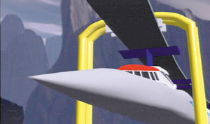
Artist’s conception of the Magnetrain as it enters a station.
Courtesy of Magnetrain |
Magnetrain, a patented magnetic levitation system for high-speed rail, promises an efficient passenger and freight-handling system to develop the world, link continents, and solve urban traffic congestion. |
|
|
|
Rail is by far the cheapest mode of land transportation. Measured in dollars per ton-mile of goods carried, conventional rail freight is approximately ten times cheaper than trucking. Until the 1950s, most of the long-distance freight carried overland in the U.S.A. travelled by rail. Trucks were used primarily for local delivery, short hauling, and certain specialty items. Rail is also the most efficient means of carrying passengers in high-density urban areas.1
It would seem obvious that the reconstruction of freight and passenger rail capabilities in the industrialized nations, and their first-time construction in the nations of the developing world, be a priority of any government wishing to serve the general welfare. Yet, it is unlikely that the rail systems of the 21st century will operate on the same principles as those we associate with railroads of the past. The steel-wheel-on-steel-rail design has served us admirably for more than 170 years. Railroads of the future will more likely use a friction-free design, employing the attractive or repulsive force of a magnet to suspend the train either above or below its track. In such systems, called magnetic levitation, the friction and noise associated with conventional, steel-wheel-on-steel-rail systems are eliminated, and much higher operating speeds and lower track-maintenance costs can thus be achieved.
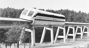
There are many ways to achieve magnetic levitation. Two systems of magnetically levitated trains have been brought to the large-scale demonstration stage as of this date: one in Emsland, Germany, where a train routinely achieves speeds of more than 400 km/hour on a 31.5-km demonstration track, and one in Japan. The German system uses electromagnets, mounted on a flange protruding inboard from the lower part of the train car, which are attracted to the underside of a large I-beam shaped rail (see photo, p. 48). The Japanese design employs a repulsive system. The motion of cryogenically cooled superconducting coils, carried in the train car, induce a repulsive field in the specially designed track, which lifts the train as it travels. In the United States, a number of other types of magnetic levitation systems have received government funding, and small test tracks have been built for them.
All of the systems so far funded use electromagnets (that is coils of wire wrapped around an iron core, which behave like magnets when electricity is passed through), to suspend, or levitate, the train. A permanent magnet is the term for a piece of iron or steel alloy that retains its magnetism without the need for an external electrical current. Although the use of permanent magnets for levitation had at times been contemplated, no designs have been brought to completion.
|
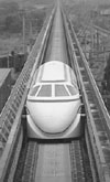
The Japanese MLU 001 on its U-shaped guideway at the Miyazaki Test Track. |
|
What Is Magnetrain?
Magnetrain is the name for a maglev train system using a permanent magnet levitation system. It was first conceived by the American inventor, Colonel (ret.) Roy D. Vinson, in 1972. At that time, the idea of high-speed rail transport using magnetic levitation was in the air. The Apollo Program, in which Colonel Vinson had played a part, had just taken man to the Moon. To move us across the Earth at speeds approaching the speed of sound, silently suspended from rails by a magnetic air gap, did not seem so far-fetched an idea. In fact, a system developed by two physicists at the Brookhaven National Laboratory in 1964, proposed using super-cooled, superconducting coils to achieve the magnetic levitation. (This was the system which the Japanese government was to adopt about a decade later.)
Colonel Vinson was only vaguely aware of the idea of magnetic levitation at the time. He had no detailed knowledge of any of the systems then being contemplated. Driving down the Los Angeles freeway with an engineer friend one day, it occurred to him that a permanent magnet of sufficient strength might provide an ideal way to levitate a train car. “But how would you keep the magnet from grabbing on to the track?” his friend asked him. He didn’t know the answer, but the problem had gotten hold of him. A short time later, finding himself a casualty of the massive wave of layoffs then striking the aerospace sector, he found himself with the time to attack the problem.
In World War II, Vinson, a regular Army officer, served as a Major in armor with the 15th Army of General Gerow, and the 3rd Army of the legendary General George S. Patton, Jr. He was known among the officers and men as “George Jr.,” not because of any close relationship to Patton, but because, as he puts it, “we thought alike.” Vinson describes himself as an “annihilationist,” in the tradition of General Ulysses S. Grant. It is the theory that the purpose of warfare is to destroy the enemy’s warfighting capability as fast as possible, to the end of bringing about an end to the war, by unconditional surrender, as soon as possible. This theory of warfare suited his personal temperament, Vinson says. Whenever he confronted a problem, whether personal, intellectual, or military, he attacked it with all the forces at this command, until he had conquered.
Such was his approach to the challenge of levitating a train car using permanent magnets. After many false starts, of which he says “I will never reveal them, because they are so foolish,” he came to the solution. The train would be suspended by the force of permanent magnets from two parallel steel rails suspended from towers above the ground. To solve the problem of preventing the magnets from grabbing onto the rail, he would use sets of, not one, but two magnets. The principal magnets, holding up the weight of the car, would be attracted to the rail above. But a second magnet, of lesser strength, would act in repulsive mode to create a small air gap between the principal magnet and the rail. A pair of these sets of magnets would be contained within a levitation compartment above the train. Perhaps six or eight such pairs would be positioned above each train car.
|
|
|
The reader can get a feel for the essential idea behind this new levitation system by holding a strong magnet under a fixed steel object. The magnet will try to attach itself to the steel. Now, with the other hand, push the hand holding the magnet, away from the steel object. It will be seen that there is a small air gap in which the magnet is neither fixed to the steel, nor free to move away from it. It is a region of attraction.
The second problem was to find a means of maintaining and adjusting that air gap as the train car underwent changes in weight, as a result of loading and unloading, or from aerodynamic stresses. This, Colonel Vinson solved, by using a system that had become familiar to him from experience in the automotive and aerospace industries— hydraulics. The attractive and repulsive magnets would be mounted on pistons, themselves contained in oil-filled cylinders. The oil in these two cylinders would be in communication with a third cylinder, the weighing cylinder. The cargo or passenger compartment of the train would be suspended from structures, in the shape of inverted-U’s, attached to a pair of pistons which would press down on the weighing cylinder like a shock absorber in a car.
|

Colonel Vinson explains the working of his hydraulic control system to Anna Shavin, a collaborator of 21st Century. |
|
|
Colonel Vinson’s Magnetrain concept refers to the unique levitation system and the earthquake-resistant steel towers which suspend the train above grade. The propulsion of the train would be accomplished by the same means applied to existing maglev systems—that is either linear induction or linear synchronous motors. These motors are a variation of the familiar electric motor, in which a varying magnetism in the stationary (or field) coils causes continuous rotational motion of a rotor. In the linear motor variation, the stator, or field, coil is effectively stretched out over the length of the train track. A varying electrical current is supplied to the track or guideway ahead of the train’s path, in such a way that the induced magnetism results in a continuous forward motion.
How Magnetrain Works
Figure 1 is an overview of the towers and overhead track structure from which the train cars would hang. Clearance between the underside of the cars and the ground would be maintained at a minimum of 18 feet. This would eliminate the need for grade crossings in populated areas, and allow the system to pass over agricultural land without disrupting production.
In Figure 2 we see the two principal parts of the train itself, the passenger or cargo compartment (below) and the levitation compartment (above). In Figure 3 we see a slice through the place marked 2 in Figure 2. This shows us the internal workings of the levitation system.
Let us examine Figure 3 in more detail. Part number 11 is a part of the cross-structure suspended between the towers, to which the steel rail is attached; it is probably made of pre-stressed concrete. Part 12 is the underside of the I-beam shaped steel rail, which is laminated to minimize the occurrence of induced, or eddy, currents when the magnet passes near it. The lifting magnets (21) are mounted on pistons, which can travel up and down in cylinders mounted directly below this rail. Next to each of the lifting magnets, in the inboard direction, are the smaller repulsive magnets (22), also mounted on pistons contained within cylinders (42). The repulsive magnets are positioned under strips of ceramic magnets (14), which run along the length of the control track (13).
The third pair of pistons (35) is mounted in the weighing cylinders. The inverted U-shaped structure (18) supports the weight of the passenger or cargo compartment (17). When additional weight is added to the lower compartment, such as by the loading of passengers or freight, it puts a downward force on the pistons (35), forcing oil in the weighing cylinders (36) to move through the tubes (37) into the cylinders (38), which contain the attractive, lifting magnets. The lifting magnet is thus forced upward, closer to the track, as is required to sustain the weight that has been added.
However, to assure that the lifting magnet does not continue moving closer to, and perhaps grab, the track, a compensating force is introduced by means of the repulsive magnet. As the piston (39) holding the lifting magnet moves upwards, oil in the upper part of its cylinder is forced out through the connecting tube (41) into the cylinder (42), which contains the repulsive magnet. This reduces the air gap between the repulsive magnet and the strip of ceramic magnetic material which runs the length of the track, thus providing a compensating force to push the train away from the track. The levitation compartment is thus lowered with respect to the track. Gravity will force the passenger or cargo compartment to fall as well. That must cause a downward pressure on the oil in the weighing cylinders, causing the entire cycle just described to repeat itself.
The levitation of the train is thus a closed-loop system, controlled by hydraulic means. When the weight of the vehicle is increased, the hydraulically activated pistons adjust their positions to return the system to equilibrium with the levitation magnets slightly nearer the tracks. When the weight of the vehicle is reduced, the vehicle tends to move upward, causing fluid to flow from cylinders (42) into the upper part of cylinders (38), and from thence into the weighing cylinders (36). The net result is for the vehicle to be in equilibrium, with the levitation magnets slightly more distant from the tracks.
The hydraulic system for control of the magnets is unique. In the German and Japanese systems, very complex electronically controlled feedback devices are required to maintain the proper relationship of train and track. In the Magnetrain system, the closed hydraulic loop does this job. This may be supplemented by an additional system that would allow the magnets to react to very sudden changes in load, such as could be encountered from sudden wind gusts, or on turns. The original Magnetrain patent proposes a variety of ways to accomplish this. Basically, a sensor will detect a change in the air gap between the primary lift magnet and the track. Then, in one version, the information can be fed to an electromagnetic coil which is wound around the lift magnet. The amount and direction of the current flow through the coil will be proportional to the change in air gap detected by the sensor. In this way, the flux of the lift magnet can be increased or decreased, almost instantaneously.
The Magnetrain system is the only one which requires no additional electricity at all to maintain lift. The atomic electrical circuits, which make up a permanent magnet, never have to be replenished.
|
|
The German Transrapid on its test track, at 500 km per hour.
|
|
Some Comparisons to the German and Japanese Maglevs
The German Transrapid 07 operates on-grade with a heavy track support structure, and a track that must be maintained to a very high-degree of flatness. To levitate the train, the track of the Transrapid flares out at the top, while flanges on the underside of the train cars reach around underneath the flare. Electromagnets, mounted in the wraparound flanges, then provide the lift, by pulling the train up towards the underside of the flared part of track. This type of maglev is known as an Electromagnetic Suspension System, or EMS.
The Japanese maglev train, the HSST, uses superconducting electromagnets to induce an electromagnetic repulsive force in the track, causing the train to levitate. This type of system is known as Electrodynamic Suspension, or EDS. The design is a variation of the one first worked out in 1966 by U.S. physicists James Powell and Gordon Danby of Brookhaven National Laboratories. Cryogenically cooled superconducting magnets in the train cars induce a current in the guideway (track) as the train moves forward. The induced current, by Lenz’s law, creates a repulsive magnetic force which lifts the train off the guideway. Since the lifting force only becomes strong enough at about 30 km per hour, the train must use conventional wheels for takeoff and landing. The refrigeration systems needed to maintain superconduction are bulky and expensive. Another possible drawback is that passengers are exposed to very high-gauss magnetic fields below their feet. In Magnetrain, the magnets are isolated in a separate levitation compartment, above the passenger compartment.
One of the big advantages of Magnetrain over the existing German and Japanese systems is that Magnetrain is the only one that is designed for functioning above-grade. In the German and Japanese system, the train pulls or pushes itself from a complex track that must rest firmly on the ground. Elevating these trains is a very expensive proposition. Magnetrain is designed to hang from earthquake-resistant steel towers at a minimum clearance of 18 feet above the ground. Thus there is no problem of grade-crossings, one of the leading causes of train accidents today.
In cross-country applications, Magnetrain could cross over roads and farmers’ fields without disrupting activity. Perforated metal mesh nets under the train would dissipate air flows, preventing dangerous air currents in areas where there is likely to be contact with human activity. The design is also particularly suited to crossing desert terrain, where sand accumulation can easily disable on-grade train systems.
In urban and suburban applications, the trains would run at less than the 600 mile-per-hour top speeds. In congested areas, the steel towers could be built right over existing roadways. Unlike the old urban elevated trains, they would make little noise, and the sleek design of the towers and track would cause little disruption of light. In the highly congested greater Los Angeles area, for example, Magnetrain inventor, Colonel Vinson, envisions construction of Magnetrain towers on the rather generous rights of way of existing freeways. Vinson has been a resident of California for more than 30 years, and is thus acutely aware of the threat posed by earthquakes. For this reason, he believes a subway system is fundamentally unsound for any earthquake prone location on the Pacific rim. In the 1981 patent, the basic design of a system of earthquake-resistant support towers is revealed. Since then, his friend and collaborator, engineer Theodore Anvick, who is a specialist in design of towers, bridges, and large structures, has worked out many refinements. The essential idea, embodied in the original patent, is illustrated in Figure 4. The portion of track running between each successive tower is a distinct segment. The cross support which holds up the track is not rigidly affixed to the tower. Rather, it is attached to the top of the tower structure by a male and female cone. In the words of the patent: “The purpose of these cones is to make a secure horizontal alignment of each segment with adjoining segments, and to regain such alignment, if disturbed by Earth movements.”
|
|
|
The Magnets
When Colonel Vinson began the work of designing the Magnetrain system in 1972, he was unaware of any magnet capable of supporting a train in the way he envisioned. Unbeknownst to him, a physicist by the name of Carl Strnat, working at the Air Force research laboratory in Dayton, Ohio, had just recently demonstrated the feasibility of a very powerful, new type of magnet made out of an alloy of Samarium, Cobalt, and Iron. Samarium is one of the Lanthanide series of elements that falls between atomic numbers 57 and 70. They are known as “rare earths,” a misnomer since they are neither “rare” nor “earths.” The secret to the new type of magnets lay in Dr. Strnat’s insight into the crystal anisotropy of alloys made with rare earth elements. Essentially, the peculiar crystal structure causes the iron atoms to be “frozen” in place, such that they are not disoriented when exposed to countervailing magnetic forces.
The measure of the strength of a magnet is the product of the inherent magnetic force, contributed solely by the presence of iron atoms, and its resistance to an opposing magnetic force, which is known as coercivity. The inherent magnetic force retained by a permanent magnet, after it is no longer exposed to a magnetizing influence, is known as remanence. The product of the remanence into the coercivity, known as the BH product, is a good measure of the strength of a magnet. Although a rare earth magnet can never have as high a measure of remanence as one made of pure iron, its resistance to demagnetization can be so much greater, that the end result is a much more powerful magnet.
Before 1970, the strongest magnets were of the type known as Alnico, an alloy of Aluminum, Nickel, Cobalt, and Iron. The BH product of the best Alnico magnets reached about 80 kilojoules/m3. By 1980, Samarium Cobalt magnets had achieved a BH product of about 240 kilojoules/m3, three times greater than Alnico.
In 1984, researchers at the General Motors Research Laboratory and in Japan discovered an even stronger type of rare earth magnet using an alloy of Neodymium, Iron, and Boron. Neodymium-Iron-Boron magnets now achieve a BH-product of about 400 kilojoules/m3, five times greater than any magnet existing up to 1970. These Neodymium magnets are now readily available in many sizes and shapes.
Neodymuium-Iron-Boron magnets have a lift ratio of 270 to 1 with a one-inch air gap. That means that 740 pounds of such magnets will lift a train car weighting 100 tons, making it perfectly feasible to carry freight cross-country at high speed, on a Magnetrain system.
|
|
|
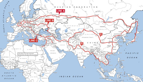
Map shows existing and probable routes of an intercontinental landbridge linking three continents, as conceived by international statesman Lyndon LaRouche. High-speed rail freight and passenger transportation is a crucial element in raising the rate of productivity of the world economy such that rapid development of the underdeveloped world can take place, LaRouche argues. Corridors of 50- to 100-kilometer width along the rail routes will be the loci of new urban and high-technology, agro-industrial development. China already conceives of such a scheme to overcome the poverty of its central interior regions. It is also a necessity for the development of Africa, where most regions are now suffering from civil war and pandemic diseases.
|
|
|
How Soon Can We Have Magnetrain?
The principal shortcoming relating to Magnetrain has nothing to do with the design or feasibility of the system. It is in the poor reception it has so far received, especially in the United States.
Magnetic levitation systems have been on the drawing boards since 1912 , when an eddy-current repulsive levitation scheme was proposed by French engineer Emile Bachelet. Beginning in the late 1960s, research and development efforts were carried out at Ford Motor Corp., Stanford Research Institute, Massachusetts Institute of Technology, and Princeton and Cornell universities, among other U.S. locations. In the 1980s, government-funded programs at a number of major U.S. aerospace corporations completed designs and scale models of various types of maglev train systems. In November 1991, the National Maglev Initiative of the Federal Railway Administration awarded $8.6 million to the Bechtel, Foster Miller, Grumman, and Magneplane corporations for development of maglev system concepts. The designs were completed in a year and reviewed in the National Maglev Initiative’s Final Report of November 1993. A number of states, including Alabama, Pennsylvania, and California have sponsored maglev study programs. Despite all these U.S. initiatives over more than 30 years, the irony is that the Germans and Japanese, with far fewer resources, persevered and completed their systems.
Colonel Vinson believes that Magnetrain will prove itself far superior to the German Transrapid and Japan’s HSST. Vinson thinks especially highly of the German maglev development effort, but because of the drawbacks earlier stated, he does not believe that either the German or Japanese systems can prove commercially viable in any large-scale application.
The next step for Magnetrain is the production of a working scale model. In the early 1990s, a major U.S. aerospace corporation approved the Magnetrain design, and came very close to funding a scale model program. At the last minute it was dropped, but not because of any objection to the soundness of the concept. In fact, the soundness of the Magnetrain levitation system has been attested by the two foremost experts on magnetism in the world, Dr. Rollin J. Parker and Dr. Klaus Kronenberg. Parker describes Magnetrain as one of the promising applications for the powerful, new rare earth magnets, in his comprehensive work on the subject, Advances in Permanent Magnetism.3
Klaus Kronenberg is a German-born physicist who, in 1948, was the first person to demonstrate that there could exist permanent magnets which did not lose their power over time. He came to the U.S.A. in the 1950s, and has worked here since. Formerly a consultant to both the U.S. and West German governments on maglev technologies, he has seen first hand the Transrapid, and many U.S. designs. About a decade ago, Kronenberg, who was living in the same area of California, met Colonel Vinson, somewhat by chance. He now believes that Colonel Vinson’s Magnetrain system is the most viable of all the existing designs. The production of a working scale model is now the priority of Vinson and his small circle of collaborators.
Vinson envisages a U.S.-led crash program to build magnetic levitation systems around the world, modelled on the Apollo Project, which he participated in, and the World War II Manhattan Project. With the proper backing from government and industry, he believes he could develop the system to where we could start installing a revenue-producing system in five years. A hero of World War II, he has never given up the vision, shared by so many Americans returning from that war, of a United States committed to using its great technical and scientific talents for the peaceful development of the world. His vision of Magnetrain is of a great instrument for uniting the people of the world, connecting continents, and improving the life of all mankind.
Laurence Hecht is Editor-in-Chief of 21st Century magazine.
Notes
1. A combination of factors led to the near-destruction of the magnificent freight and passenger railroad system, whose extension and development had been synonymous with the growth of the United States from colonial status to the world’s greatest economic power. These destructive influences included: the looting of the railroads by Morgan, Rockefeller, Harriman, and other financial interests, whereby investment in maintenance and replacement of rail and rolling stock was drastically cut, in order to produce an apparent higher rate of return on invested capital; the postwar collusion of General Motors with the oil monopolies to replace urban electric-trolley and light-rail systems with gasoline and diesel-powered buses; the construction of the Interstate Highway System, which, while not evil in itself, served as a taxpayer subsidy to cheapen the apparent cost of trucking over rail; the bureaucratic slowness of the railroads to adopt modern systems of tracking, warehousing, and freight handling.
2. U.S. Patent No. 4,307,668, Dec. 29, 1981.
3. Rollin J. Parker, 1990. Advances in Permanent Magnetism (New York: John Wiley & Sons).
|
|
|
| How Magnetrain Was Invented
21st Century editor Laurence Hecht asked Col. Roy D. Vinson how he came upon the design of Magnetrain. This is the answer the Colonel gave, in an interview conducted Aug. 23, 2000, at the inventor’s home near Covina, Calif.
Well, I had been fired from my last job in industry where I had been brought into this corporation to set up an engineering control system on two huge shipbuilding contracts for the United States Navy—an aircraft carrier and its destroyers. I had a severe difference of opinion with the director, so at the first opportunity, when they, let us say, reduced the forces, I was in the group—which I expected. At any rate, having been fired from this job, and not having another one in mind, or any desire to seek another one, because I felt I had had enough of industry, I set about something to keep my mind occupied, something I hoped would be useful.
So, one day I was driving down to San Diego with a good friend of mine, Theodore Anvick, a well known engineer, a design engineer of great ability, and also greatly appreciated throughout the world, and I remarked to Ted— I don’t know how I came to think of it, I said, “You know, Ted, if we could get a permanent magnet that was strong enough, light enough in weight, and small enough in volume, and cheap enough to produce, it occurs to me that it would be an ideal way to lift a train and the cars of a train.”
And then Ted said, “Yes, that sounds good, but how are you going to control it and keep it from grabbing the steel? How are you going to make arrangements for a difference in weight between the cars, or within any one car? How about wind gusts?”
I said, “Well Ted, I just mentioned this, if we could do all these things.”
“Yes,” he said, “Roy there’s a lotta’ ifs.”
“I’ll grant you that,” I answered, “but it just occurred to me, it would be very good if we could overcome it.”
|
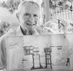 |
Colonel Roy D. Vinson on the patio of his home near Covina, California, shows off the original 1972 sketches on brown paper bag which were the kernel of the Magnetrain invention.
Laurence Hecht
|
| So, this intrigued me—and finally, very shortly thereafter, I decided I’d have a go at it, because I had nothing else really to do to occupy my mind, with, let us say, the vigor that I was accustomed to, all my life—in aerospace, and in the military field. So I set about it, and the longer I worked at it, the more aggravated I became. And, since childhood, I’ve always been aggravated by oppo3ition of any sort that the guys would want to put upon me, or whatever. . . . Finally, it had such a grip on me that I flew at this thing as I would at the enemy, in the two wars that I’ve participated in. It became my enemy. Now, mind you, at the very beginning, this was just a theory. I set up a theorem, in other words. If all these things could exist, then we could have a very, very great train system.
But, nevertheless, I didn’t think I could do it. I didn’t flatter myself that I could, and I knew nothing of maglev systems. I didn’t even know what kind was being worked on. I heard rumors that the Germans and Japanese were working on some. At any rate, I continued my work and I knew I had to be able to control those magnets. That was the whole thing. I knew darned well I could lift a train, if I had magnets strong enough. But control, that was my huge problem, and I kept working away. Finally it occurred to me that if I had some method, just a natural method without any fancy computers and electrical stuff—I have never had any affinity for electrical work, just absolutely no feel for it, don’t like it even yet, at least, to work with it.
So, finally one night—I had been working hard that particular night, and I went to bed about one o’clock. And I woke up very clear about one-thirty and I wondered, why did I awaken? So I went into the kitchen and sat down at my kitchen table, and I pulled out a grocery shopping bag, the kraft paper bag, you know, and a number two lead pencil, and I started sketching. Incidentally, I can’t make a straight line, with a ruler, even—I’m very poor at that.
At any rate, it seemed that someone else took a hold of my hand. I didn’t even know what I was going to sketch. I was just randomly sketching away there, and then, all of a sudden it hit me. An inspiration! It was that one percent, or that one tenth of one percent that Mr. Edison described—that inventions are ninety-nine percent perspiration, and one percent inspiration. So, I’ll admit, I had this inspiration, and where it came from. I don’t know. Some say it’s God’s Will, some say its Destiny, and, in any event, it came to me, and before that hour was over, I had solved it.
|
|
| Return to top |
|
|
|
|
|
|